When many older plants were built, steel and cast iron piping were common materials used underground. Although these materials have proven to have long, useful lives, improvements in plastics offer additional alternatives today. An understanding of best practices for inspecting and servicing buried piping will help you keep systems operating as designed.
Most, if not all, power plants have at least some piping systems that are located below-grade, that is, below standard ground elevation as defined at the station. In most cases, the piping is installed during new plant construction, and few people think about it again until a problem arises.
The systems range from those with minimal effect on safe plant operation, such as storm drains (although, if inadequately designed, even these can result in serious consequences), to safety-related systems, such as auxiliary feedwater piping used to supply water to steam generators at some nuclear plants if the main feedwater system is unavailable. Other important systems that are frequently underground include fire protection, service water and air, and emergency diesel generator fuel oil piping.
To be clear, there is a narrow distinction between “underground piping” and “buried piping.” Buried piping is technically a subset of underground piping. Buried piping is defined as piping that is below-grade and in direct contact with soil, whereas underground piping is below-grade, not accessible, and outside of buildings. Underground piping could, for instance, be contained within a concrete vault, which may not be designed to accommodate personnel and may not be routinely accessible.
High-Profile Problems
While air and service water leaks at coal or biomass plants don’t usually cause a media frenzy, underground fuel oil leaks can generate environmental concerns, and tritium leaks at nuclear plants can result in public relations nightmares.
Tritium is a mildly radioactive type of hydrogen that occurs both naturally and during the operation of nuclear power plants. Water containing tritium and other radioactive substances is released from all nuclear plants under controlled, monitored conditions. The releases are planned and documented. Nuclear Regulatory Commission (NRC) regulations place limits on these releases to ensure the impact on public health is very low. However, public confidence can be easily shaken when unintended releases occur.
In 2006, the NRC created a task force to examine the issue of inadvertent, unmonitored releases of radioactive liquids containing tritium in response to incidents at the Braidwood, Indian Point, Byron, and Dresden power plants. The focus of the task force was on releases that were neither planned nor monitored.
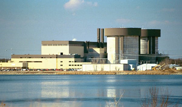
The case at Braidwood (Figure 1) received a lot of attention from the media as well as from state and federal elected officials. The problem came to light in March 2005 when the Illinois Environmental Protection Agency notified Exelon Corp.—owner of Braidwood as well as the Byron and Dresden plants—that tritium had been found in wells in a nearby community.
After months of investigation, Exelon attributed the contamination to historical leakage of vacuum breaker valves along the circulating water blowdown line at Braidwood. The blowdown line is an underground pipe that carries wastewater, including tritiated water at times, about 5 miles from the plant to the Kankakee River. It contains 11 vacuum breaker valves spaced along the length of the line. Ultimately, groundwater monitoring in the vicinity of the valves indicated that six of the valves had leaked at some point in time.
The Byron station identified similar problems in February 2006. Elevated tritium levels were detected in several of its vacuum breaker valve vaults, which are located along approximately 2.5 miles of its circulating water blowdown line. The problem at Dresden was a bit different, but was also related to underground piping leaks. In its case, contaminated water leaked from pipes connected to the plant’s condensate storage tank.
Although the NRC determined that effluent release limits were not exceeded and that the leaks did not present a health and safety hazard to plant personnel or to the public, in March 2010, Exelon settled three separate civil complaints that the Illinois attorney general and the state’s attorneys of Will, Ogle, and Grundy counties had filed jointly as a result of the tritium releases. The company agreed to pay civil penalties totaling $628,000 and an additional $548,000 to fund several supplemental environmental projects in and around the communities where the power plants are located.
Events like this highlight the importance of having a comprehensive underground pipe inspection program. Exelon, for its part, has come a long way since those days. Now it is seen as a model company when it comes to underground piping. Neil Sheehan, public affairs officer for NRC Region I, said Exelon is enclosing much of its buried piping in concrete vaults now, and the company is very proactive in trying to prevent similar incidents.
Uncovering Solutions
David Smith, technical executive in the Balance of Plant Corrosion Team at the Electric Power Research Institute (EPRI), noted that nuclear plants have focused their buried pipe integrity inspections on the most vulnerable and significant piping.
“The nuclear power industry has taken a full programmatic approach,” Smith told POWER.“They’ve developed programs. They’ve inventoried their assets. They’ve risk-ranked those assets with respect to not only level of susceptibility to corrosion issues, but also with respect to consequence of failure. The high-risk, high-consequence piping is where they have focused most of their inspections.”
EPRI has been helping the industry by doing some valuable research. In addition to providing programmatic guidance, reference materials, and a risk-ranking tool, EPRI is investigating buried pipe inspection technologies, some of which were developed by the oil and gas industry.
Modification is usually required to adapt inspection technologies for use in what some have called the “spaghetti bowl” of piping found at power plants. Unlike the miles of straight lines frequently found in the oil and gas industry, which usually include launch and retrieval stations for “pigs” (devices inserted into pipelines to do a variety of tasks, including cleaning and inspecting the pipe), power plants often have valves and elbows that make tasks more difficult, but the results have been positive.
With Exelon’s help, EPRI developed guidance for the use of one such tool, which utilizes guided wave technology. Guided wave technology uses ultrasonic guided waves to detect flaws, such as corrosion, in buried pipes. Exelon was one of the first utilities to use the technology on its underground piping.
The way it works is that a probe is mounted on the outside surface of a pipe (Figures 2 and 3). A guided wave is generated that travels some distance along the pipe. Changes in wall thickness reflect the wave. The technique can effectively survey a long run of pipe from a single location, reducing the amount of excavation necessary and helping focus work in areas known to be deficient.
However, various factors can influence the effectiveness of guided wave technology. Pipe geometry, coating type and thickness, soil loading, backfill material, buried depth, and pipe content all affect sensitivity and coverage capabilities. Often, those variables are not known until the examination is performed, so the length of pipe that can be inspected is not known until the results are obtained.
With Exelon’s assistance, EPRI created parameters to judge the effectiveness of guided wave examinations. The EPRI report Buried Pipe Guided Wave Examination Reference Document (10119115) specifically addresses items such as data acquisition and analysis for guided wave examination of buried pipes in nuclear power plants. But it hasn’t stopped there. EPRI is continuing to explore ways to use guided wave technology to inspect past piping elbows.
More Than Just a Nuclear Concern
The fact is that leaks don’t just happen at nuclear plants; they can happen in underground piping anywhere. The Big Stone Plant—a 475-MW coal-fired station in eastern South Dakota—was commissioned in 1975, so most of its buried piping has been in the ground for more than four decades. The original material used in many of the lines was steel or cast iron, which are both susceptible to corrosion, and the original installation practices have caused some additional problems.
“In particular, it seems the air lines were not originally bedded in gravel, so drainage isn’t adequate,” said Jeff Endrizzi, plant manager of the facility. “When excavated, we often find these lines pitted and pocked due to corrosion.”
Leaks are not always easy to find either. The clay content of the soil at the Big Stone site is very high. As a result, air and water leaks can migrate a significant distance in either direction from the leak location.
Dan Oakes, fuel supervisor at the plant, recalled one such instance. “We began digging where air bubbles were coming up through a crack in the paved road. We dug straight down and found the air line, but we ended up following the line about 25 feet before finding and repairing the leak. We then backfilled with gravel, so in the event that we need to work in this area again, locating and repairing leaks will be much easier.”
Repairs have varied from installing a boot over a leak to replacing a small portion of pipe to replacing significant sections of line. When repairs have been necessary, the plant has tried to swap out the original pipe with an appropriate corrosion-resistant material (Figures 4 and 5), such as PVC (polyvinyl chloride) or HDPE (high-density polyethylene). Results have been very good.
Cast Iron Versus Thermoplastic Pipe
Although management at the Big Stone Plant has decided to convert some of its systems to PVC and HDPE, cast iron pipe is still a very suitable solution for many fluid systems. According to Dave Parney, executive vice president for the Cast Iron Soil Pipe Institute, it is even required by building codes in some jurisdictions.
Gray cast iron pipe is primarily used for drain, waste, and vent plumbing applications, while ductile iron pipe—a form of cast pipe developed in 1948—is used in water and wastewater systems. There are many examples of cast iron pipe that has been in service for more than 150 years, including one water system that French King Louis XIV had installed, which was used for 330 years.
One of the benefits of using cast iron is that there are fewer problems related to expansion and contraction when compared to a plastic product. Parney said that cast iron expands and contracts similarly to concrete and steel, so competing forces are minimized. It also has better crush loads for underground installation. Cast iron is up to 10 times stronger than thermoplastic materials, so it does not need to rely on the compaction of the sidefill to support the pipe wall.
For example, based on an American Society for Testing and Materials standard, the trench for a thermoplastic pipe is required to be the width of the pipe outside diameter (OD) plus 16 inches or the OD times 1.25 plus 12 inches. Therefore, a 6-inch thermoplastic pipe requires a trench roughly 20 inches wide, whereas a cast iron pipe of the same size has no such minimum trench width.
There are also bedding requirements for plastic, while cast iron requires only that the trench bottom be flat to provide uniform support. Backfill used during plastic pipe installation must be compacted in 6-inch layers, with a minimum compaction density of 85% to 95%, depending on soil type. Cast iron advocates say that the extra work leads to extra cost, and when its high-strength, durability, and impact and corrosion resistance are factored in, cast iron should be in the conversation whenever buried pipe installation is considered.
Planting Problems
At least one leak at the Indian Point nuclear plant was traced back to damage that likely occurred during installation. In February 2009, Entergy plant operators conducting shift rounds observed water around a pipe penetration in the auxiliary feed pump building. After a brief investigation, it was discovered that condensate was leaking from a buried section of piping associated with the condenser hotwell reject line to the Unit 2 condensate storage tank.
Entergy determined that much of the leakage had gone through the plant’s storm drain system and flowed to its discharge canal. The area around the leak location was excavated to gain access to the pipe, the affected pipe section was replaced, and the system was returned to normal in a little less than a week’s time.
The company conducted a root cause investigation, which included sending the failed carbon steel pipe segment to a laboratory for analysis. The evaluation concluded that the protective external pipe coating that was applied at the time of original construction had failed, resulting in external corrosion in a localized area.
However, a potential contributing factor was that backfill placed around the pipe during installation contained rocks up to eight inches in diameter. Staff conducting the investigation determined that the large rocks in the backfill likely damaged the pipe coating during installation, allowing corrosion mechanisms to act on the unprotected metal surfaces.
Additionally, the section of piping was at a low point, which was close to the water table. Damp or wet conditions have a tendency to accelerate general corrosion of exposed carbon steel. Although the pipe coating applied is capable of protecting the pipe for the lifetime of the plant—testing areas of the piping in which the coating had not been damaged proved this fact—the damaged coating and wet conditions in this case resulted in a leak.
Although the backfill material used during initial construction was permitted by the specification in use at the time, one of the first corrective actions identified by Entergy was to update the specification. The company also implemented a buried piping and tank inspection program, including the use of improved inspection techniques, such as guided wave technology.
A Novel Acoustic Solution
Although not as technologically advanced as the guided wave system, a small Southern California–based company recently developed another tool for use on buried piping. The LeakTronics FLASH Leak Locating System can be used in certain situations to locate leaks in pipes ranging from 1 inch to 60 inches in diameter, and for lengths of piping as long as 300 feet. According to Darren Merlob, owner of LeakTronics, the system is very easy to use.
The leaking pipe must first be taken out of service and drained. It is easiest to have at least two openings in the line to be checked—preferably one at each end. A pull-guide tool, that is, a cord that can be more easily threaded from one end of the line to the other, is fed into one opening in the pipe with a plastic sleeve attached to the end, allowing a vacuum cleaner inserted in the opposite opening to suck the sleeve and cord through the pipe (Figure 6). The plastic sleeve is then removed and the FLASH unit head (Figure 7) is attached to the pull-guide system in its place. The cord is pulled back through the pipe, thereby easily threading the unit head in.
If the piping arrangement has restrictions, such as valves, or cannot be opened on opposite ends—prohibiting the use of the pull-guide system and vacuum cleaner—a fiberglass push rod can be used to insert the unit head into accessible areas. Once the unit head is in place, the pipe is closed on each end in order to allow a slight pressure to be applied to the line. In the case of the opening through which the unit head cord protrudes, a slide plug is provided in the kit, which allows the unit head to be pulled through the pipe while the line remains relatively pressure tight. The slide plug also facilitates connection of a pressure rig, which is used to pressurize the piping being tested to about 6 psig with air.
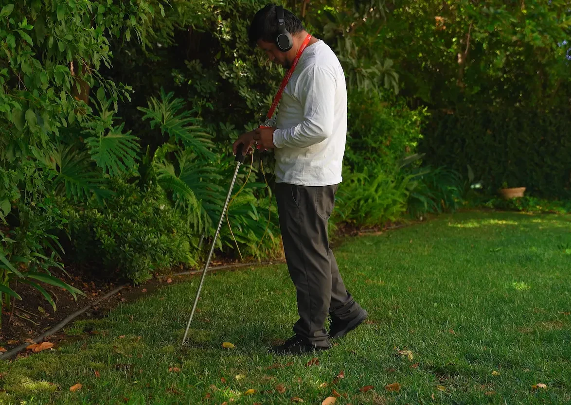
The unit head and a set of headphones are connected to the FLASH amplifier, and then the head—which contains a microphone—is slowly pulled back through the pipe while the operator listens for the leak using the headphones. When the microphone reaches the exact location of the leak, the operator will hear a distinctive jet noise. The sound identifies the location where air is exiting through the hole in the pipe.
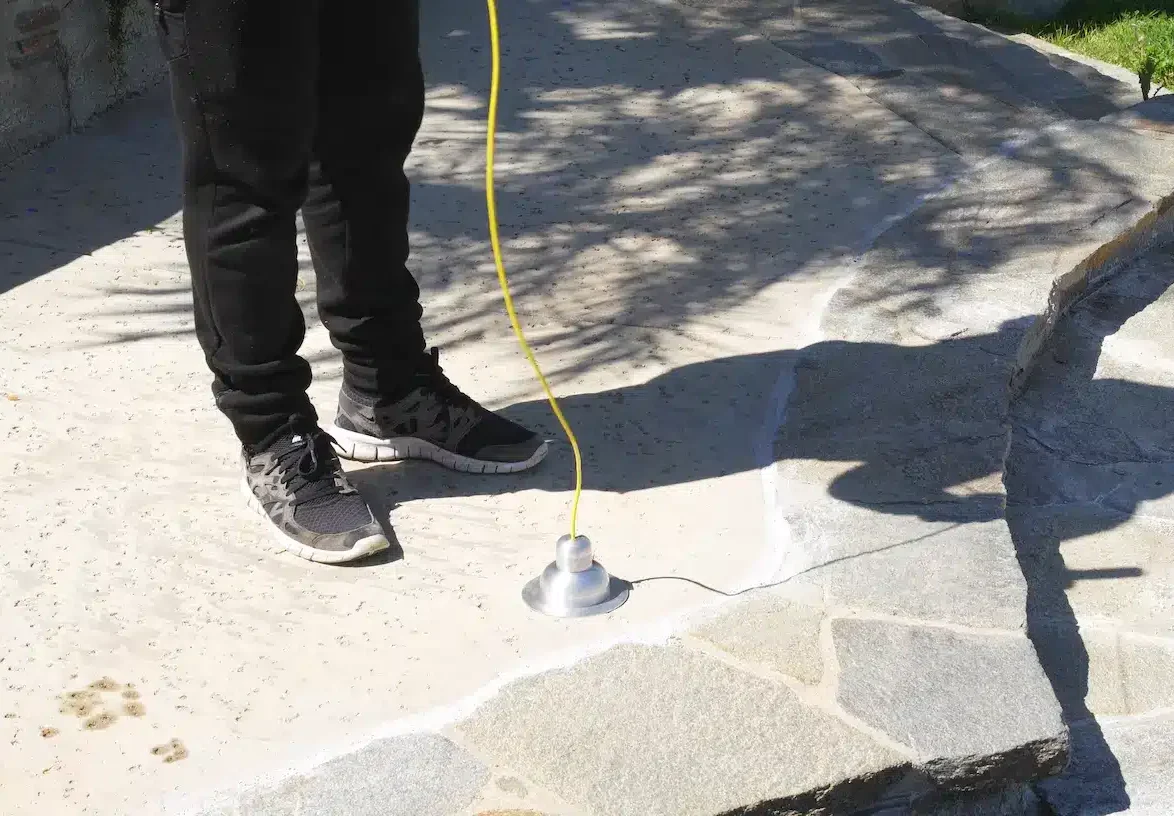
Once the leak has been found, the operator stops pulling the cable and switches the unit head connection from the amplifier to the FLASH driver. The driver emits a 512-Hz frequency signal from the unit head, which the operator then locates using the FLASH receiver. The receiver, or scanner, has an analog meter and external speaker, allowing the operator to pinpoint the spot above ground, under which the unit head is located in the buried pipe. The location is then marked and excavation can begin.
Knowing exactly where the leak is located allows excavation and repair efforts to be focused in the correct area, preventing unnecessary work, which saves time and money. This is especially important if the pipe is embedded in concrete or runs underneath pavement. Merlob says the receiver will reliably detect the unit head through 4 feet of solid concrete, and up to 15 feet of soil, depending on the type of dirt. To see an animated demonstration of the FLASH system online, visit: LeakTronics.com
— Aaron Larson is a POWER associate editor.